If you are new to the oil and gas industry, most things look the same at first: pipes, heavy steel, and big equipment. But the basic idea is simple. A well is a controlled path that connects the surface to a reservoir underground, and the job of the industry is to build that path safely, keep it stable, and then move fluids through it for years.
Because wells operate under pressure, temperature changes, vibration, and corrosion, the industry uses specialized tubulars (drill pipe, casing, tubing) and downhole tools. Most of these items connect using engineered threads, and the quality of each connection affects safety and cost. That is why connection work is treated as a controlled procedure, not just 'tightening until it feels right.'
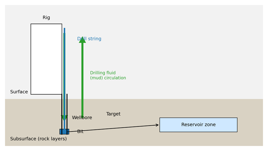
Drilling is the process of creating a hole from the surface down to the target zone. A drilling rig provides lifting capacity and rotation power. A drill string (made of drill pipe plus heavier components near the bottom) transfers rotation to the bit. The bit cuts rock, and the well deepens in stages. As drilling progresses, pipe is added one joint at a time, and the crew must repeatedly make up and later break out threaded connections.
During drilling, a key support system is the drilling fluid, often called 'mud.' Mud is pumped down the inside of the drill pipe, exits through nozzles in the bit, and returns up the annulus (the space between the drill string and the wellbore). This circulation carries rock cuttings to the surface, cools and lubricates the bit, and helps stabilize the wellbore by managing pressure. In simple terms, mud is both a transport system and a pressure-control tool.
At the surface, safety equipment provides barriers in case formation pressure tries to flow into the wellbore. One important barrier is the blowout preventer (BOP), a stack of high-pressure valves installed on the wellhead during drilling. The BOP can close around the pipe or seal the wellbore to help prevent uncontrolled flow. For a beginner, the main takeaway is that drilling is not only 'making a hole' - it is continuously balancing rock, fluids, and pressure while building a stable well.
Figure 1. Drilling basics: rig, drill string, wellbore, and mud circulation
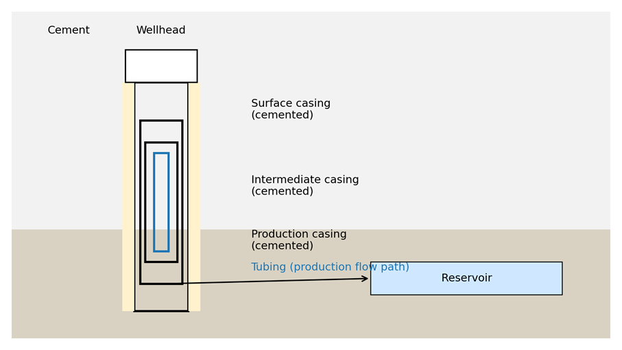
Oilfield pipes are not all the same. Each type is designed for a different phase of the well. Drill pipe is used while drilling and must be strong enough to transmit torque and tension. It is handled many times, so connection durability matters. Casing is installed after drilling a section, then cemented in place. Its job is to support the wellbore and isolate formations, so fluids do not migrate between rock layers. In simple terms, casing becomes the structural wall of the well.
After drilling is finished, tubing is installed inside the casing. Tubing becomes the main flow path for produced fluids (oil, gas, and sometimes water) to travel to the surface. Tubing can stay in the well for years and must handle pressure cycles, corrosion, and temperature changes. Completion tools (such as packers, subs, and valves) are installed together with tubing to control production. These assemblies are often built and tested in workshops where quality documentation is required.
Figure 2. Well construction: casing strings, cement, and tubing
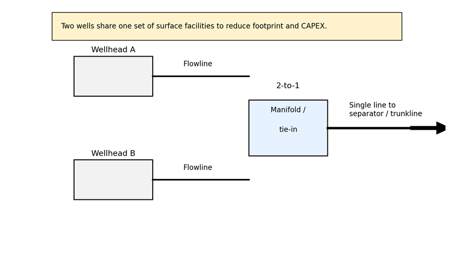
In many projects, operators build multiple wells from a single well pad. When people say '2-to-1' in a well building or well pad context, they usually mean a surface layout where two wells share one set of surface facilities. In practice, that often means two wellheads are tied into one manifold and one export line to a separator or trunkline. The goal is to reduce pad footprint, reduce piping and valves, and lower total installation cost.
A 2-to-1 tie-in is not only about saving money. It can also simplify construction and logistics: fewer trenches, fewer runs of pipe, fewer connection points to leak, and a cleaner layout. However, sharing facilities creates trade-offs. If one well needs maintenance, the shared manifold requires careful isolation planning. The operations team must also consider how flow measurement and testing are done, because two wells sharing a line may need extra valves or procedures to separate their production streams when required.
Figure 3. 2-to-1 well building concept: two wells tied into one surface line
Most oilfield tubulars and many downhole tools connect using engineered threads, typically described as a pin (male) and a box (female). These connections are designed to seal and carry load. That means the connection process must be controlled. A common beginner mistake is to treat the connection like a normal bolt: turn until tight and stop. In oil and gas, a connection can feel tight and still be wrong. It might be under-torqued and loosen or leak later, or over-torqued and permanently damaged. It might also be cross-threaded or galled because of misalignment or poor lubrication.
A practical connection procedure usually starts with identification. Confirm the correct thread type, size, and running procedure for the specific connection. Many premium connections have specific make-up rules and acceptance criteria. Next, clean and inspect. Remove debris and check the threads and shoulders for damage. Debris is a major cause of abnormal friction and can scratch sealing surfaces. Then apply the correct thread compound if required. Compound affects friction, protects against galling, and improves repeatability, so the same compound and method should be used consistently.
After preparation, the connection must be started straight. Proper alignment reduces the risk of cross-threading, and a smooth start is usually the best early sign that the connection is healthy. Many operations use a two-phase make-up. First is a spin-in phase with low torque and faster rotation to bring the parts together. Second is a final make-up phase with slower rotation and controlled torque to reach the target. Finally, verify the connection. Verification can be as simple as confirming final torque is within the allowed range, or it can include torque-turn monitoring where the system records a curve that shows how torque increased as the connection turned. Torque-turn records help detect abnormal behavior early and provide quality evidence for customers.
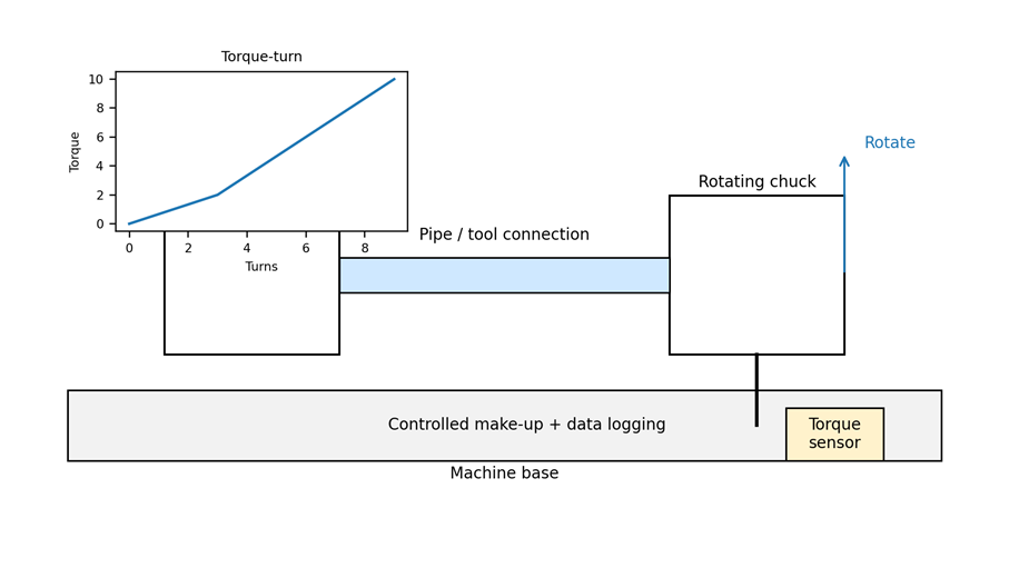
A bucking unit (sometimes called a torque machine or torque-turn machine) is a workshop machine designed to make up and break out oilfield threaded connections in a controlled, repeatable way. Instead of relying on manual tongs and operator feel, the bucking unit clamps components securely, maintains stable alignment, and applies rotation with controlled speed and torque. This is especially useful for high-value completion tools, tubing connections, and assemblies where damage or rework is costly.
Many bucking units are paired with a torque-turn system. This setup helps the operator apply make-up in a controlled, repeatable way and record the key data from each connection. The torque-turn curve acts like a simple proof of how the joint was assembled - useful for shop QC, customer acceptance, and traceability. When the clamp is stable and the turns signal is correct, the report becomes a reliable 'receipt' that reduces rework and disputes about whether a connection was made up correctly.
In a typical shop workflow, a bucking unit supports a disciplined process: clean and inspect the threads, apply the correct compound, align the parts, spin-in, final torque make-up, and then save the torque-turn record. Because the machine controls clamping and torque application, it can improve safety by reducing unexpected movement, and it can improve consistency across operators and shifts.
Figure 4. Bucking unit overview: controlled make-up/breakout with torque-turn logging
Make-up: Tightening a threaded connection to the specified final condition.
Breakout: Loosening and disassembling a threaded connection.
Casing: Structural pipe cemented in place to support and isolate the well.
Tubing: Pipe installed inside casing to carry produced fluids to the surface.
Torque-turn: A curve that records torque versus turns during make-up, used for quality evidence.
2-to-1 tie-in: A surface layout where two wells share one manifold and one export line.